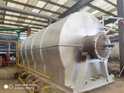
Rubber Pyrolysis To Oil
A rubber-to-oil pyrolysis machine is a piece of equipment that converts rubber into pyrolysis oil through the process of pyrolysis; it is the same equipment as a waste rubber pyrolysis unit.

Working process

The detailed process flow of Rubber Pyrolysis to Oil is as follows:
Raw Material Pretreatment and Feeding Stage: Full-size waste tires or crushed rubber blocks are fed into a closed pyrolysis reactor via manual or automatic feeding devices. After feeding, the sealed door is completely locked to ensure system airtightness. The reactor heating system is then started to begin the pyrolysis process.
Pyrolysis Start-up and Oil/Gas Generation: When the temperature inside the reactor rises to approximately 160°C, the polymer chains in the rubber begin to break, and the first-stage oil/gas mixture and non-condensable gases begin to be generated. As the temperature gradient increases, the pyrolysis reaction gradually deepens, and oil/gas production enters a stable stage.
Oil/Gas Distillation and Condensation System: The generated pyrolysis oil/gas first enters a gas distribution buffer device through high-temperature pipelines to achieve primary gas-solid separation. The oil and gas then enter the main cooling system:
Stage 1: The oil and gas undergo gravity separation through a settling pipe, with the heavy oil component being introduced into a heavy oil storage tank.
Stage 2: The distilled oil and gas enter a composite cooling pipe network approximately 400 meters long, employing a two-stage condensation design of "layered water tanks + S-shaped meandering," achieving precise condensation through water temperature gradient control.
Stage 3: The finally condensed oil undergoes multi-stage filtration before entering the finished product storage tank. The system's unique pipe design ensures nearly 100% recovery of the oil-containing components from the raw material.
Tail Gas Recycling System: Non-condensable gases that cannot be condensed throughout the process are introduced through a dedicated pipeline into a water-sealed safety device. After purification, they are transported to the reactor heater as supplementary fuel. This self-circulating design not only eliminates exhaust gas emissions but also replaces approximately 30% of external fuel requirements, significantly reducing operating energy consumption.
Flue Gas Purification Treatment Process: From the start of reactor heating, the supporting flue gas treatment system operates synchronously. The flue gas undergoes the following stages:
Primary Treatment: The Water film dust collector removes particulate matter.
Secondary Treatment: The Alkali desulfurization unit reduces sulfur oxides.
Tertiary Treatment: High-pressure atomizing spray tower for deep purification.
End Products (Take the tire cracked product as an example)
|
End product |
Yield |
Application |
|
Tire oil |
45-48% |
1. Direct sales |
|
2. As heating material |
||
|
3. Refining into diesel or gasoline by oil distillation equipment |
||
|
Carbon black |
35-40% |
1. Direct sales |
|
2. Reprocessed into toner raw materials. |
||
|
3. Reprocessed into coal or refractory briquette. |
||
|
Steel |
10-15% |
Direct sales |
|
Combustible gas |
5-7% |
1. Back to the furnace for heating the reactor. |
|
2. Stored as fuel for heating. |
Application of rubber pyrolysis to oil

Characteristics
High-Safety Design: Employing a dual-channel oil and gas pipeline system to form a double isolation barrier, and equipped with a safety water seal device, multiple pressure relief safety valves, and an intelligent early warning system, achieving closed-loop safety management throughout the entire process.
Environmentally Friendly Operation Standards: Equipped with a fully automatic slag discharge device and multiple sealing structures, ensuring zero-emission pollution throughout the production process, achieving source control and zero-pollution emissions of waste gas, wastewater, and solid waste.
High-Efficiency Cooling Solution: Innovatively adopting a water tank circulating cooling system, combined with an "S"-shaped meandering pipeline design and dual-path oil and gas pipeline parallel flow technology, significantly extends the heat exchange path and achieves more thorough temperature control and heat recovery.
Basic Parameters
|
Item |
Details |
|||
|
Model |
JZLY-1 |
JZLY-5 |
JZLY-10 |
JZLY-15 |
|
Daily Capacity |
1T |
5T |
10T |
15T |
|
Operation mode |
Batch |
|||
|
Raw Materials |
Waste Plastic, Tyre, Rubber, Oil Sludge |
|||
|
Reactor Size |
D1.4*L2.0m |
D2.0*L5.0m |
D2.6*L6.6m |
D2.8*L8m |
|
Pattern |
Horizontal & Rotary |
|||
|
Heating Materials |
Charcoal, Wood, Fuel Oil, Natural Gas, LPG, etc. |
|||
|
Total Power |
10kw/h |
18kw/h |
25kw/h |
30kw/h |
|
Floor Area (L*W*H) |
10*5*6m |
20*7*8m |
25*8*8m |
30*10*9m |
|
Operating Pressure |
Normal Pressure |
|||
|
Cooling Method |
Water Cooling |
|||
|
Life span |
5-8 Years |
|||
Workshop Showing
Customer Factory

Success case

Hot Tags: rubber pyrolysis to oil, China rubber pyrolysis to oil manufacturers, suppliers, factory